Adafruit PDM Microphone Breakout with JST SH Connector
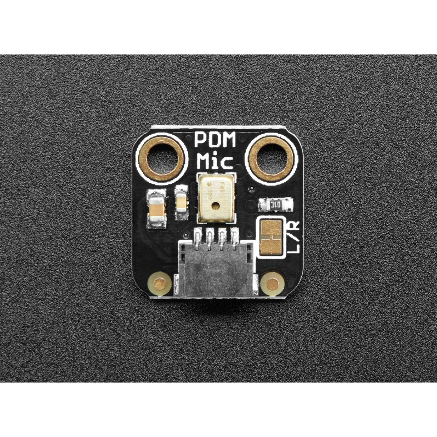
The Adafruit PDM Microphone Breakout with JST SH Connector provides a digital audio input using Pulse Density Modulation (PDM) in a compact, cable-ready form factor. The 4-pin JST SH connector (3V, GND, DAT, CLK) pairs with JST SH cables for flexible microphone placement away from the main board.
PDM works by clocking the microphone at 1–3 MHz and reading a 1-bit digital output whose pulse density represents the analogue audio signal. When filtered and decimated, this produces clean audio samples. Most modern 32-bit processors (nRF52840, RP2040, SAMD51) include hardware PDM peripherals with library support. An on-board solder jumper lets you switch between Left and Right channel output.
Key Features
- PDM Digital Output – 1-bit pulse density modulation, not analogue or I2S
- JST SH Connector – 4-pin cable-ready connector for flexible mic placement
- MEMS Microphone – Compact, high-quality digital microphone element
- 1–3 MHz Clock Rate – Standard PDM clocking compatible with most 32-bit MCUs
- Left/Right Channel Select – On-board solder jumper to choose channel
- No Analogue Input Required – Fully digital interface, no ADC needed
Integration Approaches
- Hardware PDM Peripheral – Best option: the MCU handles clocking, filtering, and decimation automatically (nRF52840, RP2040, SAMD51, etc.)
- Hardware Peripheral + Manual Filtering – The MCU provides raw PDM data; you apply decimation and filtering in software
- Analogue Filter Hack – Generate the clock externally, apply an analogue low-pass filter on the data line, and read the result as an analogue value
Ideal For
- Remote microphone placement using JST SH cables
- Voice and audio capture on digital-only microcontrollers
- Stereo mic arrays (pair two breakouts on Left and Right channels)
Also Consider
- PDM MEMS Microphone Breakout – Header version for breadboard use
Resources
- PDM Microphone Learn Guide (wiring, schematics, example code, datasheet)
Product Information
Product Information
Shipping & Returns
Shipping & Returns
Description
The Adafruit PDM Microphone Breakout with JST SH Connector provides a digital audio input using Pulse Density Modulation (PDM) in a compact, cable-ready form factor. The 4-pin JST SH connector (3V, GND, DAT, CLK) pairs with JST SH cables for flexible microphone placement away from the main board.
PDM works by clocking the microphone at 1–3 MHz and reading a 1-bit digital output whose pulse density represents the analogue audio signal. When filtered and decimated, this produces clean audio samples. Most modern 32-bit processors (nRF52840, RP2040, SAMD51) include hardware PDM peripherals with library support. An on-board solder jumper lets you switch between Left and Right channel output.
Key Features
- PDM Digital Output – 1-bit pulse density modulation, not analogue or I2S
- JST SH Connector – 4-pin cable-ready connector for flexible mic placement
- MEMS Microphone – Compact, high-quality digital microphone element
- 1–3 MHz Clock Rate – Standard PDM clocking compatible with most 32-bit MCUs
- Left/Right Channel Select – On-board solder jumper to choose channel
- No Analogue Input Required – Fully digital interface, no ADC needed
Integration Approaches
- Hardware PDM Peripheral – Best option: the MCU handles clocking, filtering, and decimation automatically (nRF52840, RP2040, SAMD51, etc.)
- Hardware Peripheral + Manual Filtering – The MCU provides raw PDM data; you apply decimation and filtering in software
- Analogue Filter Hack – Generate the clock externally, apply an analogue low-pass filter on the data line, and read the result as an analogue value
Ideal For
- Remote microphone placement using JST SH cables
- Voice and audio capture on digital-only microcontrollers
- Stereo mic arrays (pair two breakouts on Left and Right channels)
Also Consider
- PDM MEMS Microphone Breakout – Header version for breadboard use
Resources
- PDM Microphone Learn Guide (wiring, schematics, example code, datasheet)